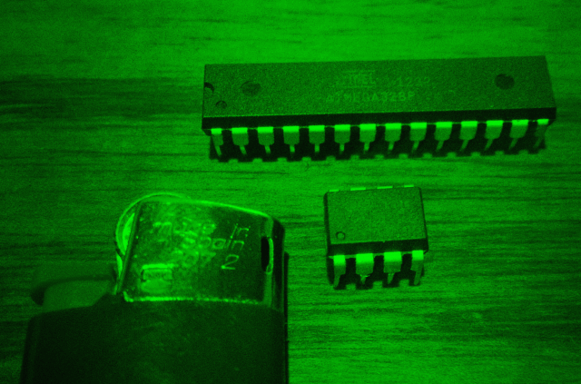
VGAXUA VGA library for Arduino UNO and MEGA 04/05/2019
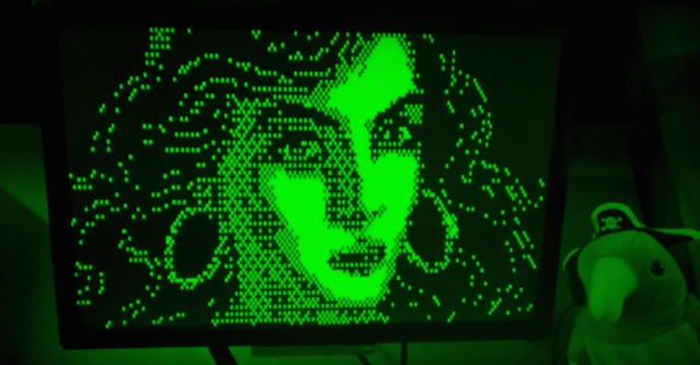
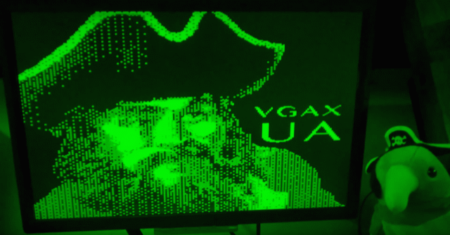
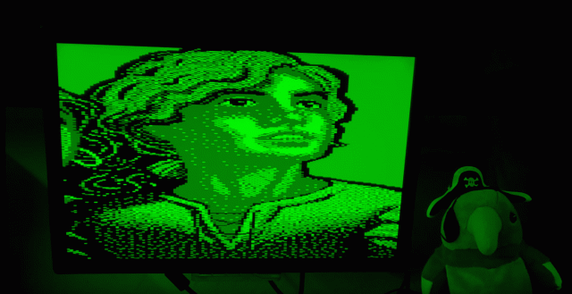
A new variant of VGAX library has born! VGAXUA is an alternative version of VGAX that can generate a VGA signal with a resolution of 192x80px with 2 colors. On Arduino MEGA resolution can be increased to 200x240px!
Check out the full documentation on my GitHub VGAXUA page
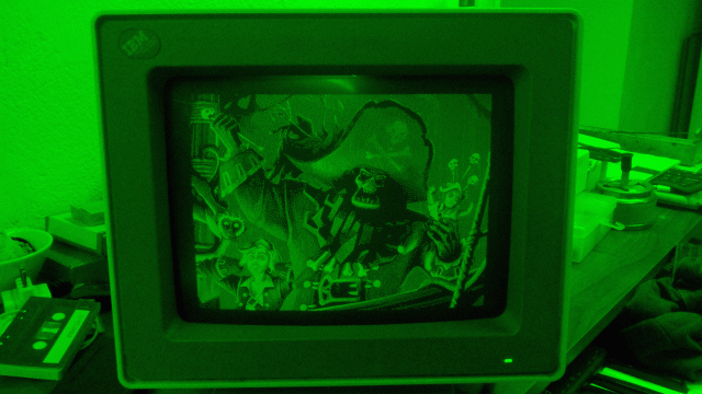
Two videos from YouTube: VGAXUA on Arduino UNO VGAXUA on Arduino MEGA
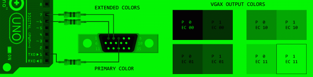
This library merge some ideas from ESPVGAX (my VGA library for ESP8266). In fact VGAXUA support extended colors toggling two PINS while generating horizontal lines. In theory is possible to control these PINS differently for each different horizontal lines but, for now, the code is limited to toggle these BITS one time for each frame.
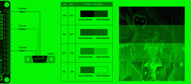
These are the colors combinations that can be achived using VGAXUA:
Now i am planning to work on a VGA signal generator that does not rely on a full framebuffer... it's a SPRITE based library!! Coming soon on The Internet :D
Happy hacking, Nerds!
VGAX Support for ATMega2560 14/04/2019
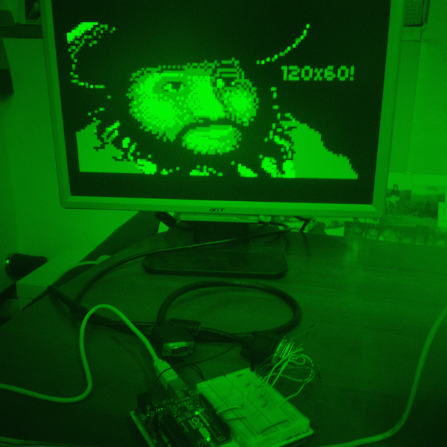
I've added support for ATMega2560 to my library VGAX! Now the library can be configured to generate 120x90px (with squared pixels) or 120x240px (rectangular pixels).
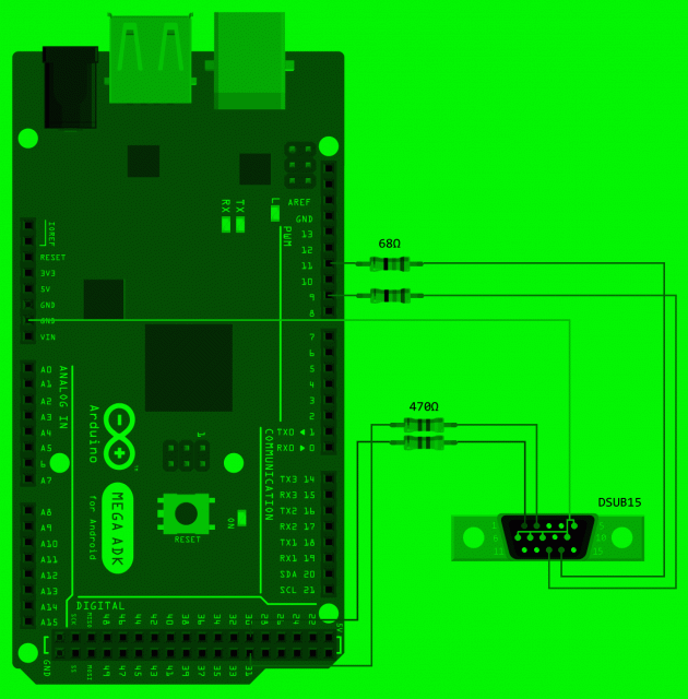
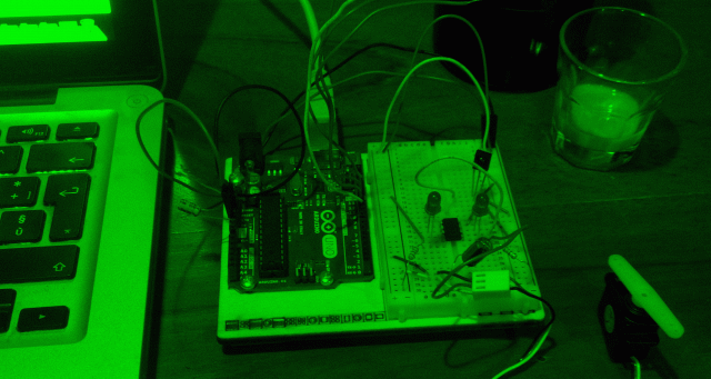
The wiring is simple, like for ATMega328. You can wire up an Arduino MEGA board with some cheap components:
To enable 120x90px resolution you need to uncomment the constant ATMEGA2560_HIGHRES on VGAX.h header. To enable 120x240px uncomment ATMEGA2560_MAXRES.
The tricky part to add support for ATMega2560 has been adapting the interrupt dejitter code. I've found that the original code, writen by Charles CNLOHR assume to work on an AVR MCU with a 16bit Program Counter. ATMega2560, like others fat MCU, has a 22bit Program Counter! So, when Charles pop PC from stack, code must be modified to pop 3 bytes instead of 2 (22bit PC requires 3 bytes):
#define DEJITTER_OFFSET 1
#define DEJITTER_SYNC -2
asm volatile(
  "     lds r16, %[timer0]    \n\t" //
  #if defined(__AVR_ATmega2560__)
  "     add r16, %[toffset]   \n\t" //
  #endif
  "     subi r16, %[tsync]    \n\t" //
  "     andi r16, 7           \n\t" //
  "     call TL               \n\t" //
  "TL:                        \n\t" //
  #if defined(__AVR_ATmega2560__)
  "     pop r17               \n\t" //ATMEGA2560 has a 22bit PC!
  #endif
  "     pop r31               \n\t" //
  "     pop r30               \n\t" //
  "     adiw r30, (LW-TL-5)   \n\t" //
  "     add r30, r16          \n\t" //
  //"   adc r31, __zero_reg__ \n\t" //
  "     ijmp                  \n\t" //
  "LW:                        \n\t" //
  "     nop                   \n\t" //
  "     nop                   \n\t" //
  "     nop                   \n\t" //
  "     nop                   \n\t" //
  "     nop                   \n\t" //
  "     nop                   \n\t" //
  "     nop                   \n\t" //
  //"   nop                   \n\t" //
  "LBEND:                     \n\t" //
:
: [timer0] "i" (&TCNT0),
  [toffset] "i" ((uint8_t)DEJITTER_OFFSET),
  [tsync] "i" ((uint8_t)DEJITTER_SYNC)
: "r30", "r31", "r16", "r17");
MCU PORTD must be changed to PORTA becouse PORTD does not have 8 pins, so all the assumptions made in VGAX for ATMega328 cannot work with PORTD for ATMega2560. Colors pins must be moved from pin 6 and pin 7 to pin 30 and pin 31 (higher 2 bits of PORTA in ATMega2560).
TIMER0 setup must be also modified to work fine on both ATMega328 and ATMega2560.
That's all! :)
ATMega2560 has 8KB of SRAM, more space for framebuffer to increase vertical resolution from 60 to 90 or 240px. In theory with ATMega2560 a new library can be created to use 256 colors (with RRRGGGBB pixel format) or 16 colors (RGBH-RGBH double pixels in single byte format). I think to try to write, in the future, these variations of VGAX inside new differents libraries (VGAX256 and VGAX16 ?).
Have fun!
Arduino ESPVGAX Library 15/08/2018
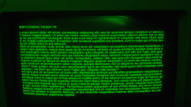
This is a VGA Arduino library for ESP8266. It can display a 512x480 image with 1bit per pixel.
Here you can download the Library code from GitHub. It's free and opensource.
Wiring
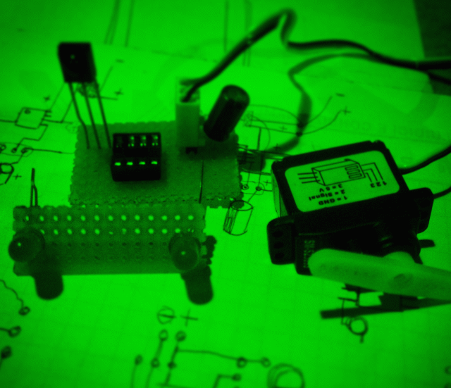
Like my VGAX Library, this Library require cheap components. You can generate a signal from an ESP8266 with less then 5$ :-)
ESPVGAX require a DSUB15 connector (aka VGA connector) and one 330Ohm resistor:
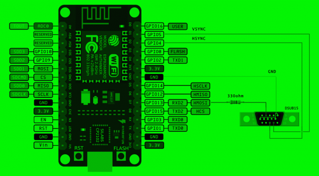
Super simple!
Colors combinations
You can wire the VGA connector in some different modes that allow you to choose your preferred white color. For example you can choose to wire it up to use black and green colors, or black and purple.
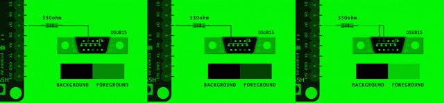
You can find more informations about colors combinations here.
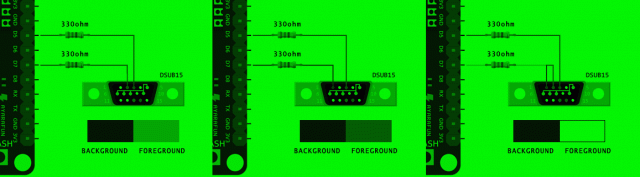
Additional colors
The Library also support two modes where colors can be increased from the standard 2 colors.
The first additional mode allow you to hook up an hardware PIN to one of the VGA pins (different from the primary color that you have selected in the first wiring). Thi hardware PIN is always ON when VGA signal pixeldata is generated, so you can change the background color from black to another color. This change is permanent and you cannot turn ON/OFF this background color variation.
The idea behind the second additional mode is this: ESP8266 HSPI can send data to VGA as a serial stream of bits, so it can only turn one VGA PIN ON/OFF at a time. But VGA timing has gaps between lines that can allow more code to be executed, before and after sending the stream of bits. So, before sending the data, the Library can turn ON/OFF some other bits and change the color combination used in each horizontal line (480 lines).
The VGA signals can become unstable if your code uses Wifi, Serial, and other Arduino classes. You can find more informations here.
Happy Hacking!
Arduino BITNINJA 09/09/2018
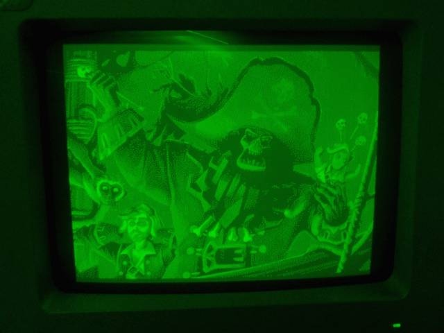
This is my first game for VGAX the VGA library that i have developed for Arduino.
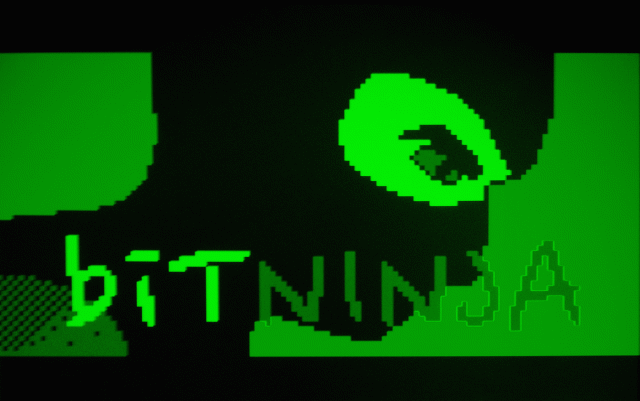
TLDR: Video of BITNINJA first test
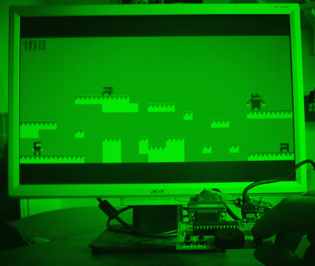
The game
This game is a small platform game, like Super Mario Bros, designed by me. After my nomination in the IOCCC 2014 Contest, i have ported some of the logic of the SMB Engine that i have developed for the Contest.
BITNINJA implements these features:
- input controller LEFT+RIGHT+JUMP with three buttons
- cutscene for splash screen, credits, introduction and epilogue
- background music for cutscene
- 5 playable levels
- collision detections
- 6 max enemies in each level
RAM Optimizations
Becouse VGAX uses 1800 bytes of RAM and the Arduino UNO ATMEGA328 MCU has only 2048 bytes of RAM, the game is optimized to use only 41 bytes of global RAM. All the images, sprites, songs and level definitions are stored in the MCU FLASH ROM. Doing the math: 2048-1800-41=207 bytes are "free", used for the MCU STACK where local variables and parameters are stored.
The 41 bytes required for BITNINJA to run are subdivided like this:
- 11 bytes for player movement and game cutscene
- 24 bytes for 6 enemies (4 byte for each enemy)
- 6 bytes for music
Sourcecode
Here you can download the BITNINJA source code !
Hardware
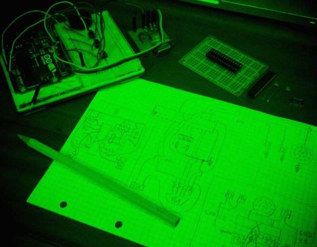
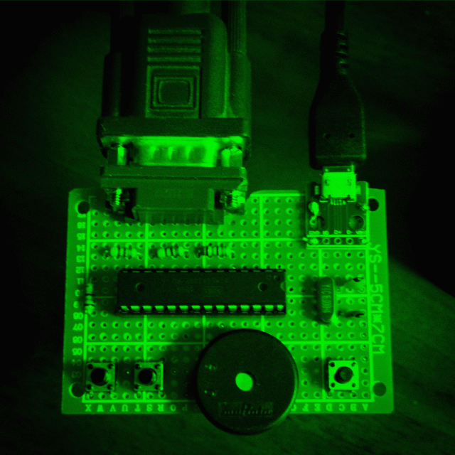
The hardware required is pretty cheap:
- a DSUB15 male connector (VGA)
- 2 68ohm resistors
- 2 470ohm resistors
- 2 22pf capacitors
- 1 16Mhz oscillator
- 3 passive buttons
- 1 audio buzzer
- 1 microusb female connector
The wiring and soldering is documented inside VGAX library documentation, except for the wiring of the standalone ATMEGA328 MCU but you can easily find online How to run ATMEGA328 standalone.
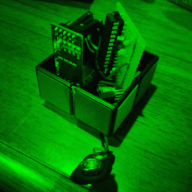
Here you can see a video of BITNINJA testing running on the Arduino UNO, before the standalone board creation. The level you see in the video is a test. The 5 levels inside the final version are different than the one in the video.
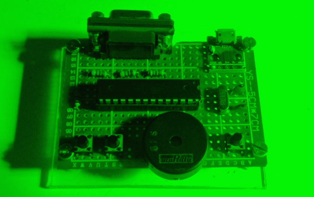
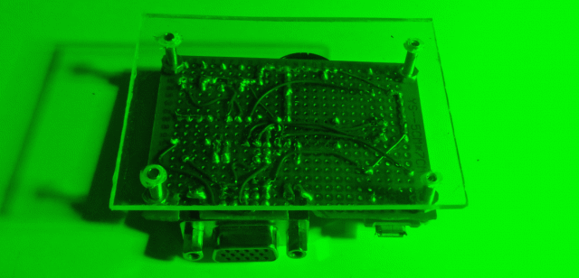
This is the final board, with a piece of plexi on the bottom:
I am planning to take a video of all 5 levels, running on the final standalone board. When i will do the video i will post it here!
Have FUN!
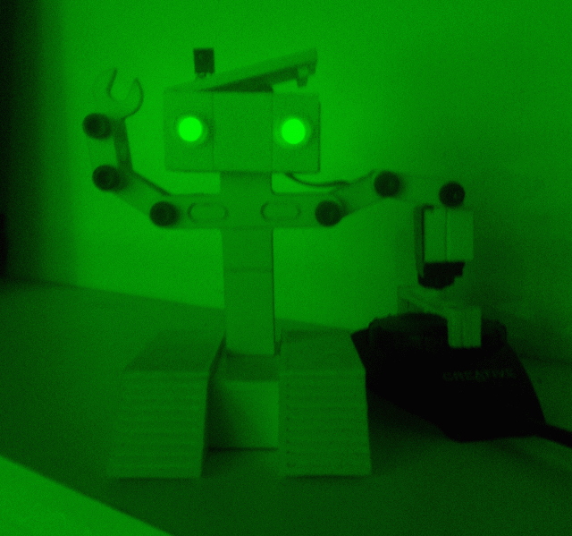
Arduino Robot UNO 09/09/2018
This is my first Arduino Robot, created in 2011!
The idea
The reason i have build it is that i need to control my audio system volume knob without phisically stand up, walk and turn the knob. I am laaazy :-D
I have a TV Remote with volume controls (and mute button) and i want to use the TV Remote to rotate the volume knob.
TLDR: Making of Arduino ROBOT UNO on Youtube!
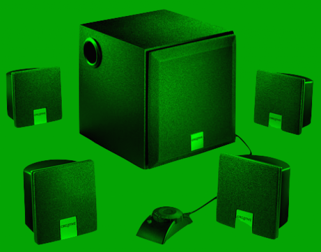
My audio system is a Creative INSPIRE Audio 4+1 Surround System that i has originally bought for my old PC. It has a volume knob to control its volume level by hand:
Hardware and Software
I have started this project by creating a tape/cardboard prototype with an Arduino UNO board, using a servo motor and an infrared receiver. Then, after some tests, i have started to modify the code so it can run on an ATTINY85 MCU, smaller than the ATMEGA328 MCU used by Arduino UNO:
I have used the Arduino UNO board to program the ATTINY85 MCU, using an online tutorial like this. Note that ATTINY85, like ATMEGA328, has an internal oscillator that can generate the MCU clock at 8Mhz or 1Mhz, so you don't need an external oscillator (or quartz) to power the MCU. In my Arduino Robot UNO i have choose to run at 8Mhz.
After that i have build the minimal circuit for the "brain" of the robot. The servo motor will be installed as one of the robot hands.
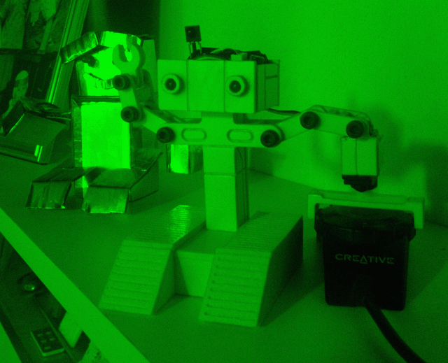
CNC cutting
I own a small CNC router that can be controlled via GCODE. At this point i have designed some sheets of plastic parts to be cutted and glued together to become the outer aspect of the robot.
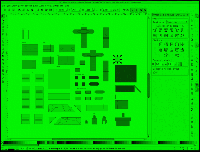
.. then i cut everythings with the CNC router ..
.. and glued all pieces together!
Here you can see the Making of Arduino ROBOT UNO, step by step.
After some weeks of testings i have notice that the batteries life was too short (3 AAA for week), so i have modified the hardware to get the 5V power from a cellular power supply. Now ROBOT UNO has a cable that go out from its head and connect to a 5V microUSB connector to the power supply.. :-D
Here you can download the Arduino ROBOT UNO sourcecode.
Design note
The ROBOT UNO design is inspired from my childhood best robot film: Short Circuit!
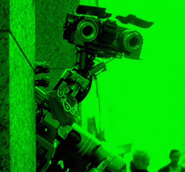
Long live Jhonny Five! Inpuuuut, MORE INPUT
Arduino Rubik Server 09/09/2018
This was my first Arduino project: A webserver inside a Rubik's cube (2x2x2 Pocket Cube version) able to solve a Rubik's Cube 3x3x3 with the Layer-by-Layer method. It is fast! Can solve any scramble in around 100msec, using only 2048 bytes of RAM (ATMEGA328 MCU)!
Coding
I am a Rubik's Cube fan. I learned how to solve the 3x3x3 standard Rubik's Cube by following this guide. But i does not follow all raccomandations and learned to solve it creating a first RED CROSS instead of WHITE CROSS.
As a programmer i have developed a simple solver in Javascript that can solve the 3x3x3 cube by using the Layer by Layer method, starting from the RED CROSS. The project was developed using Javascript, HTML5, Canvas and WebGL.
Here you can find the Smaffer 3D Cube project homepage.
After that, for the IOCCC Contest, i have ported the Javascript solver to C with some obfuscations to follow the rules of the contest.
As an Arduino fan i have also ported the obfuscated code to C++, optimizing it to use the lower amount of RAM possible, without rewriting all the code. The source code is not simple to understand.. its obfuscated.. but it works. Can solve a 3x3x3 using a standard scramble sequence.
Hardware time
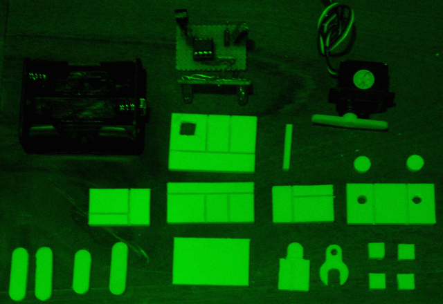
The hardware required to create this project is this:
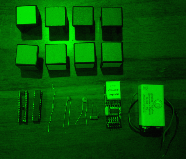
I have used the ENC28j60 breakout board to connect the Arduino ATMEGA328 MCU to Ethernet. The cube parts are from a broken 2x2x2 Pocket Cube given to me by EFFEOTTO (thanks!).
Running page
The Arduino WebServer hosted by the MCU has a simple NERDY style:
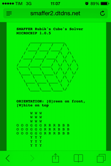
You can send the scramble sequence inside the HTTP URL. The returned page will contains the scrambled 3x3x3 cube and the list of moves to solve it.
Solving modes
The sourcecode can solve the cube in two modes: with cube rotations moves (X, Y, Z) or without rotations (in place solving). The second mode can be used, theoretically, to solve the cube phisically, using hardware motors, without full rotations of the cube (the cube stay always in the same original orientation).
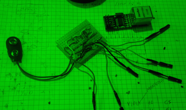
Wiring mess
This was my first Arduino project and this fact can be seen in the internal hardware soldering and wiring. But the final cube works and i think that the idea is fun and so nerdy! :-P
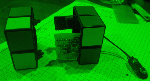
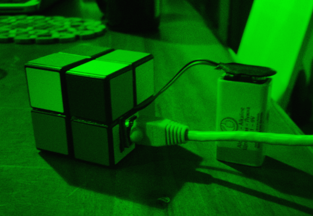
Problems
The big problem with this project, after some tests, is the battery. The idea to power up the cube using a 9V battery is not happy. The power consumption of the Ethernet connection is very high and the cube, powered with a fully charged 9V battery, cannot stay ON more than a couple of hours :-/
Future and Download
In the future, i will do a porting of this project to ESP8266, powered by a microUSB connector.
That's IT!
Here you can download the Arduino Sketch sourcecode. It is a porting of an obfuscated program so it is not simple to understand at all.. :-/
Happy hacking
Arduino VGAX Library 02/09/2018
When i have bought my first Arduino UNO i have started to test some libraries for video signal generation. One of the first interesting library was TVOut. A simple lib that allow you to generate a COMPOSITE video signal out of an ATMEGA328 MCU, using only some resistors and a COMPOSITE video connector.
VGAX Inspirations
The first inspiration for VGAX come from TVOut library: A simple VGA library for Arduino that can work with simple cheap components!
Online i have found some interesting articles about Arduino VGA video signal generation, written by Nick Gammon. These articles and his works was the starting point for the development of my VGAX Library.
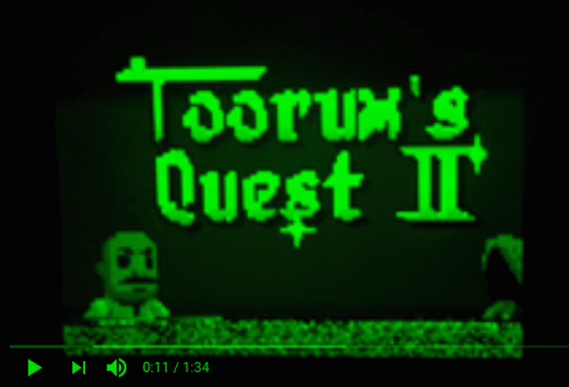
My writing of VGAX was also inspired by the work of Petri Häkkinen, creator of the game TORUM QUEST II (for ATMEGA328!!). Here a link to his Blog. Here a link to his post on the Arduino Forum.
VGAX Assembler core
The creation of VGAX was a little tricky. I've spent many nights around the interrupt jitter problem, trying to adjust some dejitter code founds online.. An Hell!
To write the Assembler core of VGAX i've studied the official ATMEL ATMEGA328 Instruction Set Manual (190 pages), searching for the best instructions to generate the PIXEL stream output without losing too many CPU cycles. The idea was to use these instructions, for each byte of the framebuffer, inside an unrolled loop
.rept 30             // output 4 pixels (unrolled loop)
    ld r16, Z+
    out %[port], r16 // write pixel 1
    mul r16, r20     // left shift 2
    out %[port], r0  // write pixel 2
    mul r0, r20      // left shift 2
    out %[port], r0  // write pixel 3
    mul r0, r20      // left shift 2
    out %[port], r0  // write pixel 4
.endr
The first good thing is that LD and MUL instructions require both 2 CPU cycles, so the output of the four pixels, packed inside a single byte, is done with the same number of CPU cycles for each pixel (3 cycles, LD=2, MUL=2, OUT=1). This equal timing ensures that all generated pixels will be displayed with the same size (horizontal width).
The second tricky thing is that the two VGA PINs are written with a single OUT instruction that writes an 8bits hardware PORT... but bits cannot be rearranged without losing time.. so the idea was to (pre)arrange the 4 pixels in one byte keeping the order of the bits aligned to the output pins of the 8BIT PORT. First pixel is stored in the higher 2 bits of byte.
![]()
The hardware PORT uses the PIN from 0 to 7 so i have wired the two VGA PINs to PIN6 and PIN7.
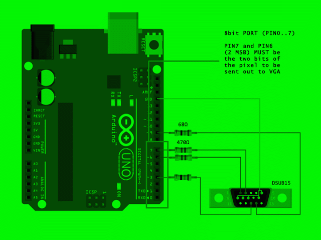
When a byte is read from the LD instruction, the first pixel bits are already on the 6th and 7th bits, ready to be written out from the OUT instruction. The next MUL will shift the second pixel bits to the right position (6th and 7th bits of the PORT) and written out. This is repeated for the remaining two pixels.
ld r16, Z+
out %[port], r16 // pixel1 bits are aligned on PORT 6th and 7th bits
mul r16, r20     // shift 2 pixel up
out %[port], r0  // pixel2 bits are now aligned
Resolution limitations
Many people ask me if is possible to increase the horizontal resolution of the VGA signal (120px).
Arduino ATMEGA328 has only 2048 bytes of RAM! The VGAX framebuffer have a resolution of 120x60px with 2bpp, almost all the MCU RAM is used (1800 bytes). This is the first limitation that cannot allow an increase of the horizontal resolution without losing color depth (2bpp). But there is another important reason that does not allow a greater horizontal resolution: the CPU speed!
ATMEGA328, inside Arduino, runs at 16Mhz. VGA signal require a 25Mhz PIXEL output speed. If you calculate the number of CPU cycles used to send PIXEL out you obtain this formula:
25Mhz : 640px = (16Mhz / 3clocks) : RES
RES = (640 * 5.3) / 25
RES = 136px~
So, the maximum resolution possible, at 16Mhz, using 3 CPU cycles for each pixel, is 136px! VGAX for ATMEGA328, with the dejitter code and the audio signal generation, reach a resolution of 120px for each horizontal line, near the maximum resolution possible.
Sharing
Here is hosted my VGAX Library, on GitHub. Here my post on the Arduino Forum.
This library was used from some people around the world. I thanks everybody for have spent some time using VGAX! Many thanks to Rob Cai that has recreated some classic games like Tetris, Pong and Breakout, using VGAX!
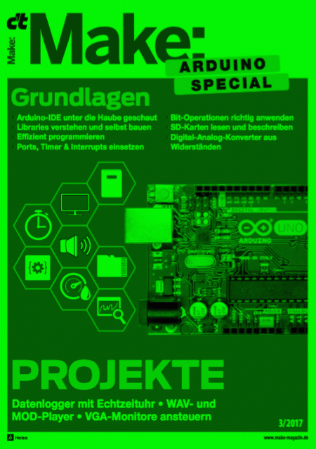
VGAX was reviewed in an article of the C'T MAKE newspaper, number of 03/2017. When i read this article i am always happy! :-)